
Disk drive enclosure
• EMU (Environmental Monitoring Unit)
• Two power supplies and blowers
• Two I/O modules (A and B)
• Fiber optic transceivers or copper cables — Loop switch configurations use only one transceiver per I/O module. New I/O modules contain only one transceiver per I/O module.


HSV controllers and enclosures
• Interface to the enclosure address bus (EAB) (Note that this is labeled as CAB.)
• Interface to the PDM.
• Data and fabric connections, including connections to the following:
- Device-side loops (There might be connections to either Fibre Channel loop switches (if present) or directly to drive enclosure I/O modules A and B.)
- Mirror ports
- Host ports
- Link status LEDs
• Power connections, noting if it is a single or dual power supply

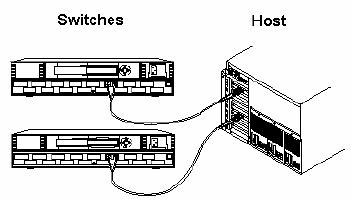
Each HSV controller is connected to both switches.

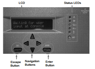
Setting up the HSV controllers
1. Enter the 16-character World Wide Name (WWN) of the node
2. Enter the two-character checksum
Using the enclosure number feature
1. Press the bottom push button to change the display to En, the enclosure number display mode.
2. Press and release the top push button to display the enclosure number.
A display of 00 indicates that the enclosure is not connected to the enclosure address bus (EAB). When this condition exists, there is no EMU-to-EMU communication over the EAB.
3. Determine the status if the display is an enclosure number in the range of 01 through 24.
A display of 01 through 14 indicates that the enclosure is physically connected
Install and Launch HP StorageWorks Command View EVA
Connecting the FCAs to the switches
You can connect the Fibre Channel cables to the FCAs at this time. The connection allows you to access any virtual disks that you create. For a multiple path configuration, use the following cabling procedure:
1. Plug one end of each Fibre Channel cable into an FCA on the server. There must be at least two FCAs.
2. Plug the other ends of the cables into the two switches.
You must plug each cable from the server FCAs into different switches.
After presenting virtual disks to the host through Command View EVA, the host can recognize EVA devices connected to the host by doing a restart or a rescan, depending on the operating system.
1. Rescan the system to make the new virtual disks accessible.
2. Select the disk type (basic only), partition, format, and assign drive letters or mount points according to standard Windows conventions after rescanning.
Adding a host to a storage system involves the following processes:
1. Collect the host information listed below:
- LAN name
- IP address (optional)
- World-Wide Name (WWN) of one FCA
- Operating system
- Custom mode number, if applicable
- Direct eventing option
2. Create a host folder.
3. Add a host.
4. Verify that the host has been added.
Presenting a virtual disk
You can present the virtual disk to a host after virtual disk creation by modifying the virtual disk properties.
Follow these steps to present a virtual disk to a host after the virtual disk has been created:
1. Expand the virtual disk you want to present and select the Active presentation in the Navigation pane.
2. Select the Presentation tab from the Vdisk Active Member Properties page.
3. Click Present.
4. Select the host.
5. Select Assign LUN (optional).
6. Select the LUN number at which the virtual disk will be presented to the host.
7. Click Finish
If you are unable to access the virtual disk, check the following:
- Verify all cabling to the switch, Enterprise Virtual Array, and host.
- Verify all firmware levels (check the Enterprise Virtual Array QuickSpecs and associated release notes for details).
- Ensure you are running a supported version of the host operating system (see the release notes).
- Ensure the correct operating system is selected for the virtual disk in Command View EVA.
Important: The standard cabling scheme is all odd-numbered ports to one switch, all evennumbered ports to the other switch.

Viewing EVA hardware properties
Using Command View EVA, view the hardware properties for the EVA storage system. The storage systems are listed by name in the HSV Storage Network folder. Select a storage system and then select a storage system rack to view properties for the rack, controller, drive enclosures, and disk drive.
• Viewing rack properties
1. In the Navigation pane, select a storage system.
2. Click Hardware → Rack [number].
• Viewing controller, drive enclosure, and disk drive properties:
1. In the Rack [number] folder, select Controller Enclosure [ID] → Controller [ID].
- What is the last digit of the World Wide Node Name entry?
- The storage system controller or base address ends in 0)
2. Click the Host Ports tab.
- What is last digit of the World Wide Name (WWN) entry?)
3. Click the Device Ports tab.
- This page displays the WWN of the controller device ports on each loop and its ALPA.
- How many ports are displayed?
4. Click the Enclosure tab.
5. Select the other controller in the Controller Enclosure folder, and review the General, Host Ports, Device Ports, and Enclosure properties.
• Viewing the disk enclosure and disk properties:
1. In the Navigation pane, select Disk Enclosure [number].
- What EMU firmware version is displayed in the Disk Enclosure Properties page?
2. Click the Power tab.
- View Power Supply 1 and Power Supply 2 properties.
3. Click the Cooling tab.
- View the Sensor-General, Sensor-Thresholds, Blower 1, and Blower 2 properties.
4. Click the IO-Comm tab.
- View the I/O Ports and Communication Buses properties. Are the ports displayed by Command View EVA in the same order as their physical configuration?
5. In the Navigation pane, click Bay [number]→ Disk Bay.
- The Disk Enclosure Bay Properties page displays in the Content pane.
6. Click the Disk Drive tab.
- What is the physical drive type?
- What is the firmware revision of the disk?
- What is the formatted capacity of the disk?
- What are the RSS ID and RSS Index settings?
Generating a configuration file
After you have verified that the configuration is the way you want it (by using LS commands) you can also use Command View EVA to visually inspect your storage system contents.
Use the CAPTURE CONFIGURATION command to create and save five configuration files. This command queries the currently selected storage system and creates five scripts that you can use to re-create the storage system configuration, including all of the groups, folders, hosts, virtual disks, and LUNs.
Use the following syntax:
Storage_System_2> CAPTURE CONFIGURATION <file_name>
For example:
Storage_System_2> CAPTURE CONFIGURATION
c:\reconfig_c2.txt
List of potential introduced problems
The following are problems that may introduce during:
- Remove device-side fiber cable from controller
- Remove cable between enclosures
- Remove cable from host fabric (not connection to appliance)
- Remove cable from host fabric (connection to appliance)
- Remove disk drive from active group
- Remove disk drive that is ungrouped
- Remove I/O module
- Remove EMU
- Remove power from controller
- Remove disk from active group, then reinsert it
- Remove EAB connection to controller
- Remove EAB cable from device enclosure
- Power off device enclosure
- Disconnect single controller port from Fibre Channel loop switch port
- Ungroup disk in active disk group
You should be able to:
+ Perform common replacement procedures
+ Perform Field Replaceable Unit (FRU) and Customer Self Repair unit (CSR) replacements
• Remove and replace the HSV controller cache battery assembly.
• Remove and replace the HSV controller blower
• Remove and replace a fiber optic cable.
• Remove and replace the transceiver.
• Remove and replace a copper cable.
• Remove and replace an HSV controller.
• Remove and replace a disk drive.
• Remove a disk drive and install a drive blank.
• Remove a drive blank.
• Remove and replace the drive enclosure power supply.
• Remove and replace the drive enclosure blower.
• Remove and replace the environmental monitoring unit (EMU).
• Remove and replace the drive enclosure I/O module.
• Remove and replace a drive enclosure.
• Remove and replace a Fibre Channel loop switch.
• Remove and replace a Fibre Channel loop switch transceiver.
0 comments
Post a Comment