| 0 comments ]


Following are major Data Protector features

High-performance backup

Data Protector enables you to perform backup to several hundred backup devices simultaneously, with support for high-end devices in very large libraries. Various backup possibilities, such as local backup, network backup, online backup, disk image backup, synthetic backup, backup with object mirroring, and built-in support for parallel data streams allow you to tune your backups to best fit your requirements.

Scalable and highly flexible architecture
Data Protector can be used in environments ranging from a single system to thousands of systems on several sites. Due to the network component concept of Data Protector, elements of the backup infrastructure can be placed in the topology according to user requirements. The numerous backup options and alternatives to setting up a backup infrastructure allow the implementation of virtually any configuration. Data Protector also integrates seamlessly with HP StoreOnce and HP StoreEver backup appliances.

Easy central administration
Through its easy-to-use graphical user interface (GUI), Data Protector allows you to administer your complete backup environment from a single system. To ease operation, the GUI can be installed on several systems to allow multiple administrators to access Data Protector via their locally installed consoles. You can even manage multiple backup environments from a single system. The Data Protector command-line interface (CLI) allows you to manage Data Protector using scripts.

HP Data Protector Architecture

Data Protector Cell Manager
An HP Data Protector cell is a set of systems with a common backup policy existing on the same LAN/SAN. The Cell Manager is the main system that is the central point for managing this network environment. It contains the HP Data Protector internal database (IDB) and runs core HP Data Protector software and session managers. The Internal Database keeps track of backed up files and the cell configuration.

Data Protector Client
A host system becomes a HP Data Protector client when one or more of the HP Data Protector software components are installed on the system. Client systems with disks that need to be backed up must have an appropriate Data Protector Disk Agent component installed. The Disk Agent enables you to back up data from the client disk or restore it. Client systems that are connected to a backup device must have a media agent component installed. This software manages backup devices and media.


Read More ...
| 0 comments ]

Objectives
• Identify new diagnostic tools
• Describe the features of the Navigator tool
• Describe the features of the Support Data Collector tool
• Describe the features of the EVA performance monitoring tool
• List the replaceable components

Review of troubleshooting tools


Replaceable components
Customer self repair (CSR) components are noted where applicable below
• Controller components
   – Controller
   – Operator control panel
   – Cache battery (CSR)
   – Controller blower (CSR)
   – Controller power supply (CSR)
• Fibre Channel loop switch
  – Fibre Channel loop switch
• Drive enclosure components
  – Drive enclosure
  – Drive enclosure power supply (CSR)
  – Drive enclosure blower (CSR)
  – EMU
  – I/O module
  – Disk drive (CSR)

Read More ...
| 0 comments ]

Objectives
• List the primary features of active-active configurations
• Describe the different performance paths used during activeactive presentation
• List the ways in which virtual disk ownership is transferred
• Describe the active-active failover model

Overview of active-passive failover mode
• EVA 3000/5000 series supports active-passive (AP) mode per LUN
• Allows one controller to actively present a given LUN
• LUNs are statically distributed among controllers
   – Preferred to certain controllers
   – Done through user interface or server
• Problematic mode of operation
   – Uses mechanisms to move a unit from one controller to the other controller in the array
   – Not an industry standard
• Failover on EVA 3000/5000 series is controlled by Secure Path or native software (Tru64/OpenVMS)

Background on active-active failover mode
• SCSI standard mechanism for controlling LUN presentation and movement was developed in 2000-2001
   – Developed by Sun, HP, and others
   – Called Asymmetric Logical Unit Access
   – HP implementation is called active-active (AA) failover
   – There is a single HP AA specification for EVA and MSA
• AA implementation
   – Only operating mode for the EVA 4000/6000/8000 series going forward
   – Also supported on other arrays: MSA, VA, XP
   – Not supported on MA/EMA
   – Not supported on EVA 3000/5000 series at present, but a future release

Active-active failover features
• Allows host access to virtual disks through ports on both controllers
• Both controllers share traffic and load
• If controller fails, second controller takes all of traffic
• Controllers pass commands to appropriate controller
• Operation is transparent to the host
• Performance penalty for using non-optimal path to the LUNs, on reads more than writes
• Performance paths can be discovered and transitioned from one controller to the other by implicit internal mechanisms or through explicit SCSI commands
• Controller/LUN failover is automatic
• Enables multipath failover software for load balancing, for example
   – PVLinks — HP-UX native failover
   – Secure Path — HP-UX V3.0F (contains AutoPath)
   – QLogic failover driver — Linux
   – MPIO — Windows and NetWare
   – MPxIO — Solaris
   – Veritas dynamic multipathing (DMP) — HP-UX and Solaris
• Enables customer-preferred HBAs
   – For example, native IBM, Netware or Sun
   – Standard drivers
• Requires all array ports to be active

AA impacts
• HP Fibre Channel ecosystem impact
   – Multipath software, BC, CA, and Data Protector (DP)
   – Changes are the most complex NSS has ever attempted
• Secure Path impact
   – Secure Path provides assist to BC, CA and other applications
   – Support needs to be picked up by firmware or application
• Customer impact
   – Co-existence between Secure Path and native multipath software
   – Co-existence between arrays
   – Upgrade or migration from first generation to second generation EVA

AA performance paths
• Each virtual disk is owned by one of the controllers, providing the most direct path to the data
• Optimal and non-optimal performance paths
  – Read I/Os to the owning controller
     • Executed and the data is returned directly to the host
     • Direct execution reduces overhead, creating an optimal performance path to the data
  – Read I/Os to the non-owning controller
     • Must be passed to the owning controller for execution
     • Data is read and then passed back to the non-owning controller for return to the host
     • Additional overhead results in a non-optimal performance path
  – Write I/Os
     • Always involve both controllers for cache mirroring, therefore
     • Write performance is the same regardless of which controller receives the I/O

Virtual disk ownership and transitions
• Virtual disk ownership is established when the virtual disk is created
• Ownership and optimal performance path can be transferred from one controller to the other in these ways
   – Explicit virtual disk transfer by commands from a host
   – Implicit virtual disk transfer (invoked internally)
        • Occurs when a controller fails and the remaining controller automatically assumes ownership of all virtual disks
        • Occurs when array detects high percentage of read I/Os processed by the non-owning controller — Maximizes use of the optimal performance path
• When virtual disk ownership is transferred, all members of virtual disk family (snapshots included) or DR group are transferred

AP failover model
First generation EVA failover, using Secure Path or Tru64/OpenVMS
• Active-passive
• Normally one controller “owns” each LUN
• Data for the owned LUN flows through one controller
• LUN1 is preferred to CI
• LUN2 is preferred to C2
Dotted line means it’s visible but not in an active state.
Controller preferences are as follows:
• No preference
• Preferred A/B
• Preferred A/B failover
• Preferred A/B failover/failback
Second generation EVA failover, using other failover software (not SP)
• Active-active
• Each LUN is primary to one controller
• Data for the owned LUN flows through the primary controller

Full-featured definition for MPIO
• Full-featured offered free of charge and supports the following
   – Automatic failover/failback — Always on, you cannot change
   – Load balancing (two implementations)
       • Load across all paths
       • Single preferred path with all other paths as alternate
   – Path management — Selecting a preferred path prevents any load balancing
   – SAN boot
   – Path verification
   – Quiesce
       • Only able to switch from a single active path to an alternate path
       • Changes preferred path setting
• Full-featured (continued)
   – Add/delete without reboot
   – LUN persistency
   – Notification
   – Integrated with performance monitoring
• Note: Implementations vary by OS

Notes on failover functionality:

• If you have a virtual disk set to the same preferred controller and preferred active path in MPIO, and it fails
over to a path on the other controller, when that path returns it fails back regardless of failover/failback or failover only settings for the virtual disk.
• If you have a virtual disk set to the other controller than the preferred active path in MPIO, and failover occurs, when the path returns, it does not fail back regardless of the settings for the virtual disk.

Multipath status
• Windows
– Windows MPIO device-specific module (DSM)
– Version 1.00.01 added support for Windows Server 2003 x64 Edition
– Basic not offered, full featured only
– Full-featured DSM at no charge
• HP-UX
– PVLinks — OS native failover
– HP Secure Path V3.0F (containing AutoPath)
– Veritas dynamic multipathing (DMP)
• Linux
– QLogic full-featured failover driver
– QLogic multipath driver supports AA today, but does not have all the features customers are used to in Secure Path

Host configurations for AA
• Similar procedures to AP
• Instead of Secure Path, use multipath software for the OS

Read More ...
| 0 comments ]

Objectives
• Identify the deployment options for Command View EVA
• Describe the Command View EVA GUI functionality changes
• List storage system scripting utility enhancements

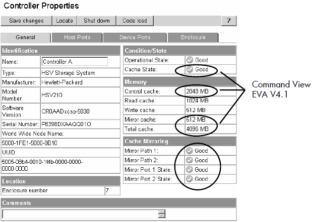
Controller attributes:
New attributes displayed for Controller Properties
• Two mirror paths
• Two mirror states
• Cache breakdown (Command View EVA V4.1)
• Three temperature sensors
• One average temperature display
• One voltage indicator
• Battery life predictions
• Four cache battery modules with two states for each: charger and battery.
All cache is now reported through this and System properties pages. Definitions are as follows:
• Control cache — the amount of memory available to store and execute controller commands in megabytes (policy memory).
• Read cache — The capacity of the read cache memory in megabytes.
• Write cache — The capacity of the write cache memory in megabytes.
• Mirror cache — The capacity of the mirror cache memory in megabytes.
• Total cache — The total capacity of the controller memory (cache and policy) in megabytes.


Additional controller host ports and host port type
Ports are displayed based on model of controller
• HSV200 — two host ports
• HSV210 — four host ports
Displayed in Controller Properties page, Host Ports tab
• EVA 3000/5000 series firmware only supports switched fabric host port connections
• EVA 4000/6000/8000 series products offer both switched and loop connections


Port loop position attribute
Sequential loop position of all controller and disk drive nodes is now displayed
• Shown in two places in the GUI
– Controller Properties page, Device Ports tab
– Drive Enclosure Bay Properties page, Disk Drive tab
Loop ID: The ID of the controller on this loop, in hexadecimal format. Example: 7C.
Operational State: If the disk device port Operational State is failed, an Enable Port Pair button appears. After you fix the port problem, click the button to re-enable the port. See operational states.
ALPA: Arbitrated Loop Physical Address, in hexadecimal format. The lower the ALPA number, the higher the arbitration priority. Example: 02.
Loop Position: The sequential physical position of the port within the arbitrated loop cabling.

System options
– Configure event notification button
– Configure host notification button
– Set system operational policies button
– Set time options button
– Shut down button
– Uninitualize button

Three-phase snapclones
• Operations that support three-phase snapclone
   – Creating an empty container from scratch
   – Converting a normal virtual disk into a container
   – Creating a snapclone using a preallocated container
   – Deleting a container
   – Displaying a container in the tree
   – Displaying a container’s property page
• These operations are conditionalized to prevent improper actions in certain situations
    – Example: Cannot create container if not enough space in disk group
• Existing virtual disk events are used with the new actions and the container object
Notes:
      • You cannot create a container if there is not enough space in disk group
     • The virtual disk cannot be converted if it has been presented or if it is a virtual disk with snapshots or with snapclones in progress, or is in process of being deleted.
      • You cannot delete a container if a delete is already in progress. The container properties always display if it exists.
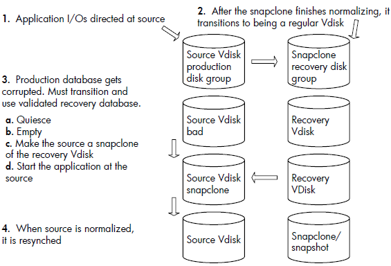
When you create a snapclone (a copy of a virtual disk), the first step is to allocate the same amount of space as the source virtual disk for the copy. Depending on the size of the source virtual disk, the space allocation may take several minutes to complete. However, you can allocate the required space before you create a snapclone, using a container, which is an empty virtual disk. Using this method is called creating a preallocated snapclone.
Creating a pre-allocated snapclone requires the following steps:
    • Create the container.
    • Clear the write cache.
    • Attach the container to the source virtual disk.
When you create a container, you assign a name to it, select a disk group, and select a VRAID level and size. That space is then reserved until you are ready to create the snapclone. You can create multiple containers to have ready when you need them. Clearing the write cache means that you set the cache policy to "write-through" when you are ready to create the snapclone. This ensures that the controller writes data to both the cache and the physical disk while the host is writing data to the virtual disk. When you attach the container, you are copying the data from the source virtual disk to the container.

First step is to create a container
• Container can be in any disk group, even different from source virtual disk
• The container redundancy and disk group fixes those attributes for the snapclone
Notes: The initial understanding was that the selected container and the active virtual disk needed to be in the same disk group. This is a snapshot restriction (no support in Command View EVA V4.X) and not a snapclone restriction.

Creating the snapclone
• After selection of container, you get prompt for change of the write cache setting
• If not in write-through, cancel, change to write-through, and create the snapclone
Changing source virtual disk write cache policy to write-through
Last step:
Redundancy (not shown here) and disk group are determined by the container redundancy and location

Snapshot redundancy limitations
• Redundancy level of a snapshot depends on the parent virtual disk redundancy
• Snapshot must be an equal or lesser redundant VRAID type than the parent
   – VRAID1 parent, valid snaps are VRAID1, VRAID5, and VRAID0
   – VRAID5 parent, valid snaps are VRAID5 and VRAID0
   – VRAID0 parent, valid snaps are VRAID0
• All snapshots of the same parent must be of the same VRAID level
   – Example: For a VRAID5 parent, all snapshots must be VRAID5 or all snapshots must be VRAID0
• Command View EVA enforces the rules
• VRAID5 source virtual disk allows only VRAID5 or VRAID0 snapshots

Integrated logging facility data
• Limitation on first generation EVA
– Integrated logging facility (ILF) logging only on an ungrouped disk
– Drive should be new — never been used on an EVA, therefore no metadata
• Second generation EVA
– New Field Service page allows you to save ILF data as a file on the management server
    • Because of long upload time, restrict the size of the ILF disks
    • 36GB is maximum, but smaller (9–18GB) is better
– Storage system can be initialized or not
– If using a drive, same limitations as first generation EVA
Go to https://hostname:2381/command_view_eva/fieldservice Select the storage system, click Save ILF Log File.

Read More ...
| 1 comments ]

Objectives
• Name the new snapclone features and functions
• Describe the three-phase snapclone process
• Describe the snapclone replica resynch process

Virtual storage terminology overview
Same terminology as for first generation EVA
• storage system (cell) — an initialized pair of HSV controllers with a minimum of eight physical disk drives
• disk group — a group of physical disks, from which you can create virtual disks
• redundant storage set (RSS) — a subgrouping of drives, usually 6 to 11, within a disk group, to allow failure separation
• virtual disk — a logical disk with certain characteristics, residing in a disk group
• host — a collection of host bus adapters that reside in the same (virtual) server
• logical unit number (LUN) — a virtual disk presented to one or multiple hosts
• virtual disk leveling — distribution of all user data within the virtual disks in a disk group proportionally across all disks within the disk group
• distributed sparing — allocated space per disk group to recover from physical disk failure in that disk group

Physical space allocation
• Physical space allocated the same as for the first generation EVA
• Physical space allocated in 2MB segments (PSEGs)
• Chunk size is 128KB (256 blocks of 512 bytes each), fixed
• One PSEG is equal to 16 chunks (16 X 128KB = 2MB), or 4096 (16 X 256) blocks


Disk groups, virtual disks, and metadata
Same definitions and specifications as first generation EVA
• Disk groups
   – Maximum of 16 disk groups per EVA8000, 14 for the EVA6000, and 7 for the EVA4000)
   – Maximum number of physical disk drives is the number present in the system up to 240
• Maximum is 56 for the EVA4000
• Maximum is 112 for the EVA6000
• Virtual disks
   – Maximum of 1024 virtual disks (first generation EVA was 512)
• Metadata
   – Storage system metadata (quorum disks)
   – Disk group metadata

Snapshots and snapclones
• Current types for the EVA 3000/5000 series
   – Traditional (fully-allocated) snapshots
   – Demand-allocated (virtually capacity-free) snapshots
   – Virtually instantaneous snapclone
• Improvements for the EVA 4000/6000/8000 series
   – Three-phase snapclone
   – Snapclone replica resynch (snapclone resynch to source)
   – Both improvements require container commands
        • Three-phase snapclone requires creation of empty container
        • Replica resynch requires a change into an empty container
   – Only snapclones can use the containers at present

Container: pre-allocated space used as a receptor of snapclone data.
The layered application called Fast Recovery Solution (FRS) required the new snapclone options called three-phase snapclone and replica resync.
FRS is an HP-supplied solution to provide a non-disruptive backup of a MS Exchange database and a timely recovery in the case of a production database failure. FRS allows the following:
• Ability to create and verify a point in time backup copy of a database while production database is servicing the application
• Ability to recover, in a timely manner, from a database that has been logically corrupted (logical corruption refers to the fact that the database is corrupted, not hardware).
Mechanisms to support FRS also provide the functionality to other user applications.

Three-phase snapclone
Three-phase process
1. Create an empty (pre-allocated) container
2. Cache flush — Write-through mode transition
   a. Flush controller cache
   b. Set cache from write-back mode to write-through mode
   c. Notify host of completion
3. Flick-of-a-switch commit
– Instant association of empty container as snapclone
– Transition source virtual disk to write-back mode
– Up to 10 snapclones at one time
• Note: Once a snapclone is completed, it can be converted to an empty container and re-used
Here is a description of the three phases in the picture.
• The first phase represents an active production database, and the pre-allocation of an empty container for later use as a snapclone. This could take place a day or a week before its actual use as a snapclone, but needs to occur far enough in advance for the creation of the empty container to complete and finish its background allocation work.
• The second phase represents transitioning the parent virtual disk to write-through and applications flushing their caches, in preparation for a flick-of-the-switch commit.
• The third phase shows the flick-of-the-switch association of the pre-allocated empty container as a snapclone, and the transitioning of the source virtual disk back to write-back mode. This flick-of-the-switch commit could have happened atomically for multiple snapclones—one per parent virtual disk.

Snapclone replica resynch
• Allows you to revert to a previous point-in-time copy (snapclone) if a virtual disk becomes corrupted
• Allows any virtual disk to be resynched to any virtual disk as long as they match in size, do not participate in sharing relationships, and the target is not presented
• Assumption: you take periodic backup snapclones
• Process includes these steps
– Quiesce the application
– Change the source (corrupted) virtual disk into an empty container
• SET VDISK CHANGE_INTO_CONTAINER command • Creates an empty container with the same settings as the original (corrupted) virtual disk

• Process includes these steps
– Restore the virtual disk data by creating a snapclone of the previously taken backup snapclone
• When the new snapclone completes, it becomes an independent virtual disk with the same settings as the previously corrupted virtual disk
• Data is as current as your most recent backup snapclone
– Restart application on source virtual disk
– Should only be a few minutes of impact
Here is a description of the replica resynch process step by step:
• In the first step, the replication of the production database is shown through a snapclone mechanism.
• In step two, when normalization completes, the recovery database is now its own virtual disk on a separate set of disks. At this point, a validation program is run against the recovery database to make sure it is a clean valid copy, ready to be used as a recovery database.
• The third step shows what happens when the production database fails. The application is quiesced or crashes in response to the logically corrupted database. An empty command is sent to the production database which leaves the storage fully allocated, but empty of data. At this point, the source virtual disk is attached to the recovery virtual disk or database as a snapclone and the application is restarted. This has a number of effects. All of the data in the recovery database can now be read through the production database which is now a snapclone of the recovery database. Writes that come into the production database, if they go to a location in the production database that has not normalized, go through a copy before write, prior to the write completing. In the meantime, background normalization proceeds from the beginning of the recovery virtual disk to the end.
•When it completes, the association of the source virtual disk and the recovery virtual disk is broken, with the recovery virtual disk in the exact same state it was in at the beginning of the recovery. So it is still a valid
recovery database.
• The last step shows the final resynch at the end of the normalization process.
Note: you can do the resynch across disk groups.

Snapclone management
•Command View EVA and SSSU are not the primary platforms to use for three-phase snapclones and replica resynch
• Three-phase snapclone and replica resynch is mainly targeted toward layered applications
– Fast Recovery Solutions
– Data Protector
– Replication Solution Manager

Read More ...